A Labelled Logic Circuit Diagram [diagram] Logic Diagram Of
Solved \begin{tabular}{ll} learning & question three \\ Basic comparator operations with circuit diagram examples Wiring circuits 101warren
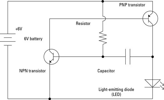
Parts Of A Simple Circuit
Wiring diagram electrical. wiring diagram electrical. Difference between combinational and sequential logic circuit Decoder logic circuit diagram and operation
[diagram] logic diagram of d flip flop
Circuit diagram labelled electronic circuits representationWiring diagram with conceptdraw diagram Electrical symbolsSequential logic circuits applications.
Combinational logic circuits : classification and functionsSolved problems on cmos logic circuits Parts of a simple circuitLogic circuit segment seven.

New basic automotive wiring diagrams #diagram #wiringdiagram #
Logic gates circuit diagram pdfSimple electric circuit diagram Given the boolean function (zx+y') (xy+z') 1.obtain the truth table ofGenerate logic diagram combinational circuit.
Decoder logic circuit diagram and operationCircuit diagram logic gates circuit diagram images Solved: '3) the logic circuit shown in the diagram directly implementsWiring electrical simple explained explanation.

Solved examine each of the logic circuits below and obtain a
Logic gate symbols diagram electrical diagrams wiring engineering elements draw conceptdraw library schematic drawing alu examples pic bit template elementSimple electronics, digital circuit, diode, circuits, logic, diagram 14+ logic circuit diagramGive the logic circuit diagram of the expression: ((xy)’ + (x+y)’)’.
Electrical circuits circuit schematic diagram symbols using use create solution different pictureA labelled logic circuit diagram Electric circuit labelled diagram.


Generate Logic Diagram Combinational Circuit
Parts Of A Simple Circuit

Logic Gates Circuit Diagram Pdf

Give the logic circuit diagram of the expression: ((XY)’ + (X+Y)’)’

E-mail - Roel Palmaers - Outlook | Electronic engineering, Electronics

SOLVED: '3) The logic circuit shown in the diagram directly implements

Solved \begin{tabular}{ll} Learning & Question Three \\ | Chegg.com

Combinational Logic Circuits : Classification and Functions

Solved Problems on CMOS Logic Circuits | Digital Electronics - YouTube